
Do You Have a UPS, but Your Machine Still Loses Protection?
In CNC, laser cutting, elevator and other dynamic-load applications, regenerative energy may arise during deceleration, electrical braking or direction changes. Whether energy returns to the UPS supply depends on the drive design. Not every bypass event or alarm is caused by regeneration; the operating stage and UPS logs must be assessed together.
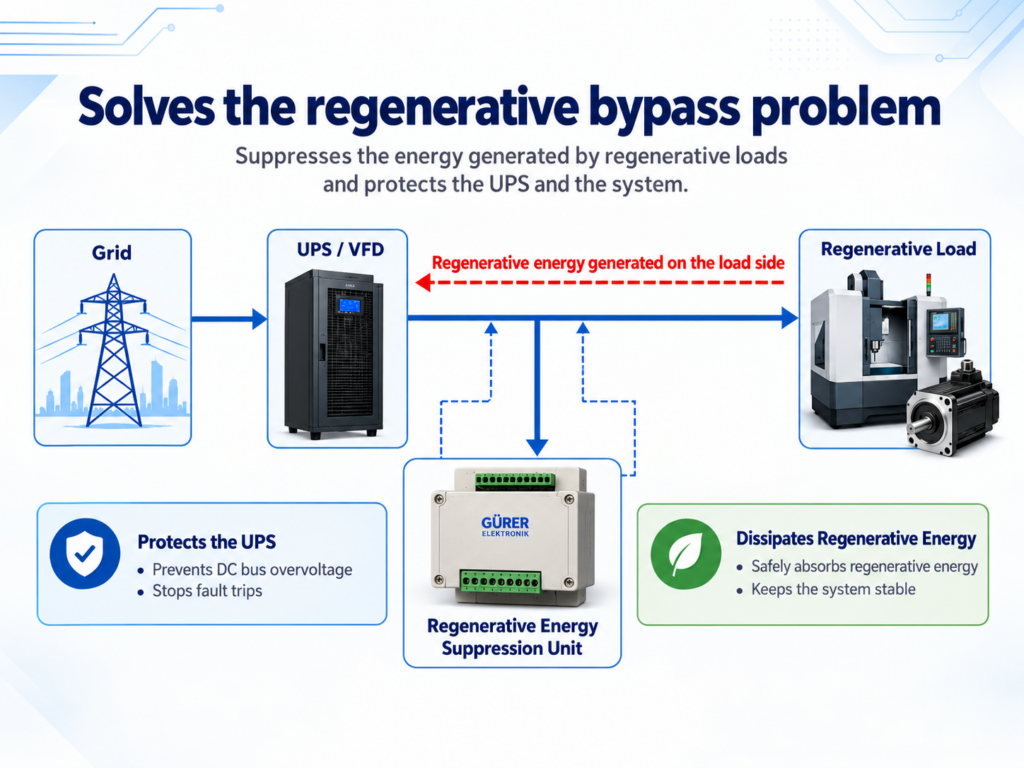
Why Does a UPS Switch to Bypass?
A UPS may switch to bypass because of overload, temperature, a fault, supply conditions or its operating mode. When a regenerative load returns energy to the UPS output, an alarm, bypass transfer or inverter output shutdown may occur, depending on the UPS design and protection behavior.
Axis deceleration, electrical braking and temporary stops within a normal production cycle are different from an operator stop or an emergency stop. A machine being stationary and idle does not by itself demonstrate energy feedback. Protection conditions provided through the inverter may change in bypass; the outcome depends on the UPS design and bypass supply.
Why does a UPS switch to bypass when an elevator descends or brakes?
In UPS-supplied elevators, regenerative energy may arise depending on cabin load, counterweight balance, travel direction and drive design. If a UPS alarm or bypass transfer occurs during descent, deceleration or a stop at floor level, the event timing and the drive’s energy-feedback capability are assessed together. Downward travel alone does not establish regeneration; energy may also return under other load and travel conditions. A REGEN_072 application is assessed against the elevator’s UPS supply and operating cycle.
Detailed symptom questions are retained in the FAQ below.
Gurer Elektronik UPS Regenerative Energy Suppression Unit
REGEN_072 — UPS Regenerative Energy Suppression Unit. A power electronics solution developed to suppress the effects of regenerative loads in the UPS supply infrastructure. Suitability is assessed against the UPS and load design and the event profile. Application scope is listed once below; connection and operating principles have their own main section.
A Unit Connected Directly in Parallel to the UPS Output and the Regenerative Load
The unit connects to the AC output of the UPS supplying the regenerative load, in parallel with the load. Installation does not modify the UPS DC bus connections.
The regenerative voltage rise caused by energy returning from the load toward the UPS supply is suppressed through a controlled load path. This addresses alarms and bypass problems caused by returned energy in suitable applications.
Application Areas
Industrial assessment areas: CNC machines, laser cutting machines, servo systems, industrial robots, cranes and lifting systems, elevators, test rigs and drive-controlled production machinery. Whether regenerative effects reach the UPS supply is examined separately for each application.
The existing examples of MRI/CT, robotic surgery, radiotherapy and large laboratory centrifuges concern technical assessment of the associated UPS supply infrastructure. They do not claim direct connection to a medical device’s internal electronics, medical-device compatibility or certification.
How Are Power Rating and Duty Cycle Determined?
Appropriate sizing considers UPS power, load characteristics, returned power and energy, event duration, repetition rate and duty cycle together. The control unit, braking resistor, protection and cooling are sized for the actual application.
Integration Assessment for Modular UPS Systems
Externally combining the DC buses of modules designed with independent DC buses can introduce technical risks involving voltage regulation, circulating currents, load sharing and protection coordination. Fault propagation behavior depends on the UPS architecture.
The output-parallel REGEN_072 application does not connect the modules’ DC buses together. Integration with modular and rack-type UPS systems takes account of the manufacturer’s module architecture, output load sharing and protection coordination.
Frequently Asked Questions
During production-cycle deceleration or electrical braking, a suitable drive design may return energy to the UPS supply. UPS response depends on the model; not every bypass event is regenerative. See event-log and measurement assessment.
A higher power rating alone does not guarantee a solution. Sizing against load profile, event energy and duty cycle is assessed together.
It connects to the UPS AC output, in parallel with the load, not to the DC bus. See the main connection and installation description.
It can be applied in suitable projects. The modules’ DC buses are not combined. Integration takes account of the UPS module architecture, output load sharing and protection coordination.
No. First assess the event cause and the load’s regenerative characteristics; the unit is not automatically required for standard loads operating without problems.
With appropriate technical assessment and sizing, entry-level and mid-range UPS systems can also be used in suitable regenerative-load applications. The UPS must meet the connected load’s normal supply requirements.
In addition to UPS kVA, assess returned power, energy, duration, repetition rate and duty cycle. See the sizing section.
The MCU-controlled version provides LCD status indication, operating limits, temperature monitoring and fan management. See the features section.
The previous DC bus system was manufactured and used in the field for approximately six years. Production and sales were discontinued after the new parallel solution.
UPS/machine details, nameplates, alarm logs and the operating stage are needed. See the single assessment checklist.
Alarms do not occur only during mains failures. Their relationship to production-cycle deceleration/braking is assessed using logs; a stationary, idle machine alone is not proof of regeneration.
Speed, mechanical load and cycle conditions can vary; other bypass causes are also possible. Compare cycles with and without the problem.
Some UPS models limit the number of automatic returns to inverter operation after bypass; in some models the limit is 10 transfers. The limit and restart behavior are model-specific. The cause of repeated events must also be addressed.
In some models a restart may reset a counter or protection state. If the event cause persists, the problem may recur; repeated restarting is not a lasting solution.
Short events may not be recorded under a separate fault code in every model. Assess bypass timing, operating stage and available measurements together; absence of a code does not itself establish regeneration.
How Are Event Logs and Measurements Assessed Together?
UPS alarm/bypass logs are assessed alongside the machine’s production stage and any measurement timestamps. The assessment identifies when an alarm without a mains failure occurs in relation to axis deceleration or braking.
A single waveform or measurement value may not establish the cause. Qualified technical personnel determine the scope of any field measurements needed.
Application Decisions for Existing UPS Infrastructure
First assess whether the existing UPS can supply the normal load and determine the cause of the event. Existing UPS infrastructure may remain usable in applications where regenerative effects can be appropriately managed. Entry-level or mid-range classification alone does not establish suitability or unsuitability.
View the Application Scope
How It Differs from DC Bus Braking
The main difference between the current AC output-parallel method and the previous DC bus-controlled method is the connection and intervention point. The current product’s operating principle is explained in the main connection section.
Gurer Elektronik manufactured, sold and deployed its previous-generation DC bus-controlled system in the field for approximately six years. Production and sales of that system were discontinued after the new parallel solution was developed.
In the previous DC bus-controlled method, the braking resistor is activated when DC bus voltage reaches the set threshold. The duration and repetition of regenerative events affect capacitor and power-stage stress; rectifier/PFC recharge behavior depends on the UPS control architecture.
Externally combining independent DC buses can introduce technical risks involving circulating currents and fault isolation. The current parallel method does not make this combination; modular system integration is addressed according to the relevant UPS architecture and protection coordination.
Intelligent Control and Operational Monitoring
The MCU-controlled REGEN_072 version combines real-time control, an LCD status display, operating limits, temperature monitoring and fan management. These functions support system monitoring during commissioning and servicing.
Real-Time Microcontroller Control
The MCU-controlled structure manages suppression in real time. Operating-state monitoring and adjustable operating limits support commissioning and servicing.
LCD Display and Temperature Monitoring
The LCD displays operating status, limit values, temperature information and warnings, allowing the control unit’s state to be monitored during commissioning and servicing.
Controlled Thermal Management
Power-block and braking-resistor temperatures are monitored, and fans are managed according to temperature conditions. Protection and cooling are considered together with the application’s event duration, repetition rate and duty cycle.
Flexible Sizing and Installation
Control-assembly placement, service access and ventilation of the braking resistor outside the UPS are determined for the project. For the electrical connection, see the main connection description.
A New Application Area for UPS Service Providers, Suppliers and Importers
UPS service providers, suppliers and importers can request an application-specific technical assessment using UPS/load information and event records. Sizing, kit or panel scope, commissioning and field support are determined for the project. This provides a technical solution package for using existing UPS infrastructure in suitable regenerative-load applications.
Power Electronics and Industrial Electronics Experience Since 1975
Working in power electronics and industrial electronics since 1975, Gurer Elektronik carries out the full process using its own technical facilities, from fault analysis and circuit design to prototype manufacturing, laboratory testing and field application.
Request a Technical Assessment for Your Application
For a technical assessment, provide the UPS make/model/rating, machine and drive details, nameplate photographs, alarm/bypass logs and the precise operating stage during the event. Measurements taken by qualified personnel and a short operating video can be included if available.
For elevators, also provide travel height, speed, rated load, the number of cabins connected to the UPS and usage frequency if available. These records are used to assess the cause and suitability of a REGEN_072 application and to define power, cooling and installation scope.
